

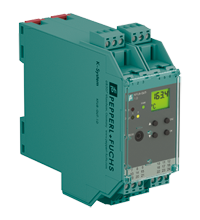
Temperature Converter with Trip Values KFU8-GUT-1.D
- 1-channel signal conditioner
- Universal usage at different power supplies
- Thermocouple, RTD, potentiometer or voltage input
- Redundant TC input
- Current output 0/4 mA ... 20 mA
- 2 relay contact outputs
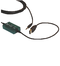
- Configurable by PACTware or keypad
- Line fault (LFD) and sensor burnout detection
- Up to SIL 2 acc. to IEC/EN 61508 / IEC/EN 61511


Please note: All product-related documents, such as certificates, declarations of conformity, etc., which were issued prior to the conversion under the name Pepperl+Fuchs GmbH or Pepperl+Fuchs AG, also apply to Pepperl+Fuchs SE.
Datablad utdrag: Tekniske data for KFU8-GUT-1.D
| General specifications | ||
|---|---|---|
| Signal type | Analog input | |
| Functional safety related parameters | ||
| Safety Integrity Level (SIL) | SIL 2 | |
| Supply | ||
| Connection | terminals 23, 24 | |
| Rated voltage | 20 ... 90 V DC / 48 ... 253 V AC | |
| Power dissipation/power consumption | ≤ 2 W ; 2.5 VA / 2.2 W ; 3 VA | |
| Interface | ||
| Programming interface | programming socket | |
| Input | ||
| Connection side | field side | |
| Connection | terminals 1, 2, 3, 4, 6 |
|
| RTD | Pt100, Pt500, Pt1000, Ni100, Ni1000 | |
| Measuring current | approx. 400 µA | |
| Types of measuring | 2-, 3-, 4-wire technology | |
| Lead resistance | max. 50 Ω | |
| Measurement loop monitoring | sensor breakage, sensor short-circuit | |
| Thermocouples | type B, E, J, K, L, N, R, S, T (IEC 584-1: 1995) | |
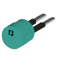
| Cold junction compensation | external and internal | |
| Measurement loop monitoring | sensor breakage | |
| Potentiometer | 0.8 ... 20 kΩ | |
| Types of measuring | 2-, 3-, 5-wire technology | |
| Voltage | 0 ... 10 V , 2 ... 10 V , 0 ... 1 V , -100 ... 100 mV | |
| Open loop voltage | max. 5 V with resistance measuring sensor | |
| Input resistance | ≥ 250 kΩ (0 ... 10 V) min. 1 MΩ (0 ... 1 V, -100 ... 100 mV) |
|
| Output | ||
| Connection side | control side | |
| Connection | output I: terminals 10, 11, 12 output II: terminals 16, 17, 18 output III: terminals 8+, 7- |
|
| Output I, II | relay | |
| Contact loading | 250 V AC / 2 A / cos φ ≥ 0.7 ; 40 DC / 2 A | |
| Mechanical life | 5 x 10⁷ switching cycles | |
| Energized/De-energized delay | approx. 20 ms / approx. 20 ms | |
| Output III | Analog current output | |
| Current range | 0 ... 20 mA or 4 ... 20 mA | |
| Open loop voltage | max. 24 V DC | |
| Load | max. 650 Ω | |
| Fault signal | downscale I ≤ 3.6 mA, upscale I ≥ 21 mA (acc. NAMUR NE43) | |
| Transfer characteristics | ||
| Deviation | ||
| Temperature effect | Input: 0.005 %/K (50 ppm) of span ; current output: 0.005 %/K (50 ppm) of span | |
| RTD | max. 0.2 % of span | |
| Thermocouples | max. 10µV deviation of CJC: ±0.8 K |
|
| Voltage | 0.1 % of span | |
| Potentiometer | 0.1 % of span when < 5 kΩ 0.5 % of span when > 5 kΩ |
|
| Current output | max. 20 µA | |
| Sampling rate | approx. 700 ms | |
| Galvanic isolation | ||
| Input/Other circuits | reinforced insulation according to IEC/EN 61010-1, rated insulation voltage 300 Veff | |
| Output I, II against eachother | reinforced insulation according to IEC/EN 61010-1, rated insulation voltage 300 Veff | |
| Output I, II/other circuits | reinforced insulation according to IEC/EN 61010-1, rated insulation voltage 300 Veff | |
| Output III/power supply | reinforced insulation according to IEC/EN 61010-1, rated insulation voltage 300 Veff | |
| Interface/power supply | reinforced insulation according to IEC/EN 61010-1, rated insulation voltage 300 Veff | |
| Indicators/settings | ||
| Display elements | LEDs , display | |
| Control elements | Control panel | |
| Configuration | via operating buttons via PACTware |
|
| Labeling | space for labeling at the front | |
| Directive conformity | ||
| Electromagnetic compatibility | ||
| Directive 2014/30/EU | EN 61326-1:2013 (industrial locations) | |
| Low voltage | ||
| Directive 2014/35/EU | EN 61010-1:2010 | |
| Conformity | ||
| Electromagnetic compatibility | NE 21:2007 | |
| Degree of protection | IEC 60529:2001 | |
| Ambient conditions | ||
| Ambient temperature | -20 ... 60 °C (-4 ... 140 °F) | |
| Mechanical specifications | ||
| Degree of protection | IP20 | |
| Connection | screw terminals | |
| Mass | 300 g | |
| Dimensions | 40 x 119 x 115 mm (1.6 x 4.7 x 4.5 inch) (W x H x D) , housing type C2 | |
| Height | 119 mm | |
| Width | 40 mm | |
| Depth | 115 mm | |
| Mounting | on 35 mm DIN mounting rail acc. to EN 60715:2001 | |
| General information | ||
| Supplementary information | Observe the certificates, declarations of conformity, instruction manuals, and manuals where applicable. For information see www.pepperl-fuchs.com. | |
Classifications
| System | Classcode |
|---|---|
| ECLASS 13.0 | 27210129 |
| ECLASS 12.0 | 27210129 |
| ECLASS 11.0 | 27210129 |
| ECLASS 10.0.1 | 27210129 |
| ECLASS 9.0 | 27210129 |
| ECLASS 8.0 | 27210190 |
| ECLASS 5.1 | 27210107 |
| ETIM 9.0 | EC002919 |
| ETIM 8.0 | EC002919 |
| ETIM 7.0 | EC002919 |
| ETIM 6.0 | EC002919 |
| ETIM 5.0 | EC001485 |
| UNSPSC 12.1 | 32101514 |
Details: KFU8-GUT-1.D
This signal conditioner provides the galvanic isolation beetween field circuits and control circuits.
The device converts the signal of a resistance thermometer, thermocouple, potentiometer, or voltage source to a proportional output current. It also provides a relay trip value.
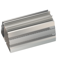
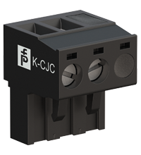
The removable terminal block K-CJC-** is available as an accessory for internal cold junction compensation of thermocouples.
A fault is signalized by LEDs acc. to NAMUR NE44.
The device is easily configured by the use of the PACTware configuration software.
For additional information, refer to the manual and www.pepperl-fuchs.com.
Datasheet: KFU8-GUT-1.D
| Datasheet | Filtype | Filstørrelse |
|---|---|---|
| Datasheet KFU8-GUT-1.D | 1306 KB | |
| Fiche de données KFU8-GUT-1.D | 1313 KB | |
| Datenblatt KFU8-GUT-1.D | 1308 KB | |
| Datasheet KFU8-GUT-1.D | 1353 KB | |
| Hoja de datos KFU8-GUT-1.D | 1316 KB |
Documents: KFU8-GUT-1.D
CAD+CAE: KFU8-GUT-1.D
| CAD | Filtype | Filstørrelse |
|---|---|---|
| CAD 3-D / CAD 3-D | STP | 2720 KB |
| CAD Portal / CAD Portal | LINK | --- |
| EPLAN | ||
| CAE EPLAN Data Portal / CAE EPLAN Data Portal | LINK | --- |
| CAE EPLAN macro EDZ / CAE EPLAN Makro EDZ | EDZ | 76 KB |
Approvals+Certificates: KFU8-GUT-1.D
| Certificates | Filtype | Filstørrelse |
|---|---|---|
| exida Functional Safety Assessment | 437 KB | |
| Declaration of Conformity | ||
| EU Declaration of Conformity (P+F) / EU-Konformitäterklärung (P+F) | 55 KB |
Software: KFU8-GUT-1.D
| Device type managers (DTM) | Filtype | Filstørrelse |
|---|---|---|
| DTM Collection Interface Technology 2 / DTM Collection Interface Technology 2 | ZIP | 32633 KB |
| Software Tools | ||
| PACTware 4.1 SP6 / PACTware 4.1 SP6 | ZIP | 43327 KB |
| PACTware 5.0 / PACTware 5.0 | ZIP | 44203 KB |
Relaterte produkter: KFU8-GUT-1.D
| Matching System Components | ||||||
|---|---|---|---|---|---|---|
|
||||||
|
||||||
|
||||||
|
||||||
| Accessories | ||||||
|
||||||
|
||||||
|
||||||
|
||||||
|
||||||


Choose from various selection criteria like safety integrity level, performance level, device function, and signal type and find the SIL/PL assessed device that you are looking for.


Pepperl+Fuchs AS
Frednesøya 21
3933 Porsgrunn
Norway
info@no.pepperl-fuchs.com
 +47 3557 3800
Pepperl+Fuchs er en ledende leverandør innen utvikling og produksjon av produkter til det globale automasjonsmarkedet. Kontinuerlig innovasjon, høy kvalitet og kontinuerlig vekst danner grunnlaget for vår kontinuerlige suksess i mer enn 70 år. Pepperl+Fuchs-konsernet har i dag mer enn 6300 ansatte globalt. Produksjonen er basert på ISO 9001 og finner sted i Tyskland, USA, Singapore, Ungarn, Indonesia og Ungarn.