

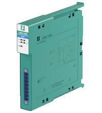
Digital Output with Shutdown Input LB6116E
- 2-channel
- Outputs Ex ia
- Mounting in Zone 2, Class I/Div.2 or in the safe area
- Line fault detection switched on and off
- Positive or negative logic selectable
- Simulation mode for service operations (forcing)
- Permanently self-monitoring
- Output with watchdog
- Output with bus-independent safety shutdown
- Module can be exchanged under voltage (hot swap)


Please note: All product-related documents, such as certificates, declarations of conformity, etc., which were issued prior to the conversion under the name Pepperl+Fuchs GmbH or Pepperl+Fuchs AG, also apply to Pepperl+Fuchs SE.
Datablad utdrag: Tekniske data for LB6116E
| Slots | ||
|---|---|---|
| Occupied slots | 1 | |
| Supply | ||
| Connection | backplane bus | |
| Rated voltage | Use only in connection with the power supplies LB9*** | |
| Power dissipation | 1.95 W | |
| Power consumption | 2.9 W | |
| Internal bus | ||
| Connection | backplane bus | |
| Interface | manufacturer-specific bus to standard com unit | |
| Digital output | ||
| Number of channels | 2 | |
| Suitable field devices | ||
| Field device | Solenoid Valve | |
| Field device [2] | audible alarm | |
| Field device [3] | visual alarm | |
| Connection | channel I: 1+, 4/5/6/8-; channel II: 7+, 4/5/6/8- | |
| Internal resistor | 258 Ω , both channels parallel 129 Ω | |
| Current limit | 40 mA both channels parallel 80 mA | |
| Open loop voltage | 23 V , both channels parallel 23 V | |
| Line fault detection | can be switched on/off for each channel via configuration tool also when turned off (every 2.5 s the valve is turned on for 2 ms) | |
| Short-circuit | < 50 Ω | |
| Open-circuit | > 10 kΩ | |
| Response time | 10 ms (depending on bus cycle time) | |
| Watchdog | within 0.5 s the device goes in safe state, e.g. after loss of communication | |
| Indicators/settings | ||
| LED indication | Power LED (P) green: supply Diagnostic LED (I) red: module fault , red flashing: communication error , white: fixed parameter set (parameters from com unit are ignored) , white flashing: requests parameters from com unit Status LED (1, 2) red: line fault (lead breakage or short circuit) , yellow: state of digital I/O (0/1) Mode LED (M) white: Parallel operation of outputs |
|
| Coding | optional mechanical coding via front socket | |
| Directive conformity | ||
| Electromagnetic compatibility | ||
| Directive 2014/30/EU | EN 61326-1:2013 | |
| Conformity | ||
| Electromagnetic compatibility | NE 21 | |
| Degree of protection | IEC 60529 | |
| Environmental test | EN 60068-2-14 | |
| Shock resistance | EN 60068-2-27 | |
| Vibration resistance | EN 60068-2-6 | |
| Damaging gas | EN 60068-2-42 | |
| Relative humidity | EN 60068-2-78 | |
| Ambient conditions | ||
| Ambient temperature | -40 ... 60 °C (-40 ... 140 °F) | |
| Storage temperature | -40 ... 85 °C (-40 ... 185 °F) | |
| Relative humidity | 95 % non-condensing | |
| Altitude | max. 2000 m | |
| Shock resistance | shock type I, shock duration 11 ms, shock amplitude 15 g, number of shocks 18 | |
| Vibration resistance | frequency range 10 ... 150 Hz; transition frequency: 57.56 Hz, amplitude/acceleration ± 0.075 mm/1 g; 10 cycles frequency range 5 ... 100 Hz; transition frequency: 13.2 Hz amplitude/acceleration ± 1 mm/0.7 g; 90 minutes at each resonance |
|
| Damaging gas | designed for operation in environmental conditions acc. to ISA-S71.04-1985, severity level G3 | |
| Mechanical specifications | ||
| Degree of protection | IP20 when mounted on backplane | |
| Connection | removable front connector with screw flange (accessory) wiring connection via spring terminals (0.14 ... 1.5 mm2) or screw terminals (0.08 ... 1.5 mm2) |
|
| Mass | approx. 150 g | |
| Dimensions | 16 x 100 x 102 mm (0.63 x 3.9 x 4 inch) | |
| Data for application in connection with hazardous areas | ||
| EU-type examination certificate | EXA 16 ATEX 0025X | |
| Marking |  II 3(1) G Ex nA [ia Ga] IIC T4 Gc II (1) D [Ex ia Da] IIIC I (M1) [Ex ia Ma] I II 3(1) G Ex nA [ia Ga] IIC T4 Gc II (1) D [Ex ia Da] IIIC I (M1) [Ex ia Ma] I |
|
| Output | ||
| Voltage | 24.2 V | |
| Current | 108 mA | |
| Power | 654 mW | |
| Internal capacitance | 12 nF | |
| Internal inductance | 0 mH | |
| Output (both channels parallel) | ||
| Voltage | 24.2 V | |
| Current | 216 mA | |
| Power | 1307 mW | |
| Internal capacitance | 24 nF | |
| Internal inductance | 0 mH | |
| Galvanic isolation | ||
| Output/power supply, internal bus | safe electrical isolation acc. to EN 60079-11, voltage peak value 375 V | |
| Directive conformity | ||
| Directive 2014/34/EU | EN IEC 60079-0:2018+AC:2020 EN 60079-11:2012 EN 60079-15:2010 |
|
| International approvals | ||
| ATEX approval | EXA 16 ATEX 0025X | |
| UL approval | E106378 | |
| Control drawing | 116-0426 (cULus) | |
| IECEx approval | IECEx EXA 16.0010X | |
| Approved for | Ex nA [ia Ga] IIC T4 Gc [Ex ia Da] IIIC [Ex ia Ma] I |
|
| General information | ||
| System information | The module has to be mounted in appropriate backplanes (LB9***) in Zone 2 or outside hazardous areas. Here, observe the corresponding declaration of conformity. For use in hazardous areas (e. g. Zone 2, Zone 22 or Div. 2) the module must be installed in an appropriate enclosure. |
|
| Supplementary information | Observe the certificates, declarations of conformity, instruction manuals, and manuals where applicable. For information see www.pepperl-fuchs.com. | |
Classifications
| System | Classcode |
|---|---|
| ECLASS 13.0 | 27210101 |
| ECLASS 12.0 | 27210101 |
| ECLASS 11.0 | 27210101 |
| ECLASS 10.0.1 | 27210101 |
| ECLASS 9.0 | 27210101 |
| ECLASS 8.0 | 27210101 |
| ECLASS 5.1 | 27210120 |
| ETIM 9.0 | EC001485 |
| ETIM 8.0 | EC001485 |
| ETIM 7.0 | EC001485 |
| ETIM 6.0 | EC001485 |
| ETIM 5.0 | EC001485 |
| UNSPSC 12.1 | 39121008 |
Details: LB6116E
The digital output features 2 independent channels.
The device can be used to drive solenoids, sounders, or LEDs.
Open and short circuit line faults are detected in on and off state.
The outputs are galvanically isolated from the bus and the power supply.
The output can be switched off via a contact. This can be used for bus-independent safety applications.
Datasheet: LB6116E
| Datasheet | Filtype | Filstørrelse |
|---|---|---|
| Datasheet LB6116E | 717 KB | |
| Datenblatt LB6116E | 717 KB |
Documents: LB6116E
CAD+CAE: LB6116E
| CAD | Filtype | Filstørrelse |
|---|---|---|
| CAD 3-D / CAD 3-D | STP | 1453 KB |
Approvals+Certificates: LB6116E
| Certificates | Filtype | Filstørrelse |
|---|---|---|
| China SITIIAS CCC Ex Certificate | 10583 KB | |
| EXA Ex i and Ex n | LINK | --- |
| Europe EXA ATEX Category (1) D ATEX Category 3 G | 366 KB | |
| South Africa MASC | 730 KB | |
| USA Canada, USA UL Certificate of Compliance cULus | 570 KB | |
| United Kingdom CML UKEX Category (1) D UK-Type Examination Certificate UKEX Category (1) G UKEX Category 3 (1) G UKEX Category (M1) | 187 KB | |
| Control Drawings | ||
| Control drawing CSA / Control drawing CSA | 320 KB | |
| Declaration of Conformity | ||
| EU Declaration of Conformity (P+F) / EU-Konformitäterklärung (P+F) | 1143 KB | |
| UK Declaration of Conformity (P+F) / UK-Konformitäterklärung (P+F) | 1038 KB |


The new LB/FB PROFINET gateways from Pepperl+Fuchs open the door for IIoT 4.0 applications in process industries.


Pepperl+Fuchs AS
Frednesøya 21
3933 Porsgrunn
Norway
info@no.pepperl-fuchs.com
 +47 3557 3800
Pepperl+Fuchs er en ledende leverandør innen utvikling og produksjon av produkter til det globale automasjonsmarkedet. Kontinuerlig innovasjon, høy kvalitet og kontinuerlig vekst danner grunnlaget for vår kontinuerlige suksess i mer enn 70 år. Pepperl+Fuchs-konsernet har i dag mer enn 6300 ansatte globalt. Produksjonen er basert på ISO 9001 og finner sted i Tyskland, USA, Singapore, Ungarn, Indonesia og Ungarn.