

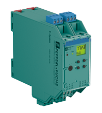
HART Loop Converter KFD2-HLC-Ex1.D
- 1-channel isolated barrier
- 24 V DC supply (Power Rail)
- HART field device input with transmitter power supply
- Usable as signal splitter (1 input and several outputs)
- 3 analog outputs 4 mA ... 20 mA
- Sink and source mode output
- Configurable by keypad


Please note: All product-related documents, such as certificates, declarations of conformity, etc., which were issued prior to the conversion under the name Pepperl+Fuchs GmbH or Pepperl+Fuchs AG, also apply to Pepperl+Fuchs SE.
Datablad utdrag: Tekniske data for KFD2-HLC-Ex1.D
| General specifications | ||
|---|---|---|
| Signal type | Analog input | |
| Supply | ||
| Connection | Power Rail or terminals 23+, 24- | |
| Rated voltage | 19 ... 30 V DC | |
| Rated current | approx. 120 mA at 24 V DC | |
| Power dissipation | 2.3 W | |
| Power consumption | 2.9 W | |
| HART signal channels (intrinsically safe) | ||
| Conformity | HART field device input (revision 5 to 7) | |
| Interface | ||
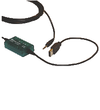
| Programming interface | programming socket | |
| Input | ||
| Connection side | field side | |
| Connection | terminals 1, 2, 3, 4, 5, 6 | |
| Open circuit voltage/short-circuit current | typ. 24 V / 28 mA | |
| Input resistance | 250 Ω , 5 % (terminals 2, 3 and with jumper on 5, 6) | |
| Available voltage | ≥ 15.5 V at 20 mA, short-circuit protected | |
| Output | ||
| Connection side | control side | |
| Connection | output I: terminals 7, 8, 9 , output II: terminals 13, 14, 15 , output III: terminals 19, 20, 21 | |
| Output signal | analog | |
| Voltage range | 5 ... 30 V , sink mode from external supply | |
| Current range | 4 ... 20 mA , (source or sink mode) | |
| Load | max. 650 Ω , source mode | |
| Fault signal | downscale I ≤ 2 mA, upscale I ≥ 21.5 mA (acc. NAMUR NE43) or hold measurement value | |
| Other outputs | HART communicator on terminals 22, 24 | |
| Collective error message | Power Rail and LED red | |
| Transfer characteristics | ||
| Output I, II, III | ||
| Resolution | max. 2 µA | |
| Accuracy | < 20 µA, 10 µA typ. | |
| Influence of ambient temperature | < ± 2 µA/K | |
| Duration of measurement/Response delay | HART message acquisition time plus 100 ms | |
| Galvanic isolation | ||
| Output I/II/III/power supply | functional insulation acc. to IEC 62103, rated insulation voltage 50 Veff | |
| Indicators/settings | ||
| Display elements | LEDs , display | |
| Control elements | Control panel | |
| Configuration | via operating buttons via PACTware |
|
| Labeling | space for labeling at the front | |
| Directive conformity | ||
| Electromagnetic compatibility | ||
| Directive 2014/30/EU | EN 61326-1:2013 (industrial locations) | |
| Low voltage | ||
| Directive 2014/35/EU | EN 61010-1:2010 | |
| Conformity | ||
| Electromagnetic compatibility | NE 21:2006 | |
| Degree of protection | IEC 60529:2001 | |
| Ambient conditions | ||
| Ambient temperature | -20 ... 60 °C (-4 ... 140 °F) | |
| Mechanical specifications | ||
| Degree of protection | IP20 | |
| Connection | screw terminals | |
| Mass | 300 g | |
| Dimensions | 40 x 119 x 115 mm (1.6 x 4.7 x 4.5 inch) (W x H x D) , housing type C2 | |
| Height | 119 mm | |
| Width | 40 mm | |
| Depth | 115 mm | |
| Mounting | on 35 mm DIN mounting rail acc. to EN 60715:2001 | |
| Data for application in connection with hazardous areas | ||
| EU-type examination certificate | BASEEFA 07 ATEX 0174 | |
| Marking |  II (1)G [Ex ia Ga] IIC II (1)D [Ex ia Da] IIIC II (1)G [Ex ia Ga] IIC II (1)D [Ex ia Da] IIIC |
|
| Supply | ||
| Maximum safe voltage | 253 V AC (Attention! The rated voltage can be lower.) | |
| Equipment | terminals 1, 4/3 (with link between terminals 4 and 5) | |
| Voltage | 25.2 V | |
| Current | 104.9 mA | |
| Power | 0.661 W | |
| Internal capacitance | 1.1 nF | |
| Internal inductance | 0 mH | |
| Equipment | terminals 2, 5/3 | |
| Voltage | < 28 V | |
| Power | < 1.33 W | |
| Voltage | 1.1 V | |
| Current | 11.9 mA | |
| Power | 4 mW | |
| Internal capacitance | 0 µF | |
| Internal inductance | 0 mH | |
| Output I, II, III | terminals 7, 8, 9; 13, 14, 15; 19, 20, 21 non-intrinsically safe | |
| Maximum safe voltage | 253 V (Attention! Um is no rated voltage.) | |
| Certificate | PF 07 CERT 1142 X | |
| Marking | II 3G Ex nA IIC T4 Gc |
|
| Galvanic isolation | ||
| Input/Other circuits | safe electrical isolation acc. to IEC/EN 60079-11, voltage peak value 375 V | |
| Directive conformity | ||
| Directive 2014/34/EU | EN IEC 60079-0:2018+AC:2020 , EN 60079-11:2012 , EN 60079-15:2010 | |
| International approvals | ||
| FM approval | ||
| Control drawing | 116-0129 | |
| IECEx approval | ||
| IECEx certificate | IECEx BAS 07.0047 | |
| IECEx marking | [Ex ia Ga] IIC , [Ex ia Da] IIIC | |
| General information | ||
| Supplementary information | Observe the certificates, declarations of conformity, instruction manuals, and manuals where applicable. For information see www.pepperl-fuchs.com. | |
Classifications
| System | Classcode |
|---|---|
| ECLASS 13.0 | 27210190 |
| ECLASS 12.0 | 27210190 |
| ECLASS 11.0 | 27210190 |
| ECLASS 10.0.1 | 27210190 |
| ECLASS 9.0 | 27210190 |
| ECLASS 8.0 | 27210190 |
| ECLASS 5.1 | 27242692 |
| ETIM 9.0 | EC001601 |
| ETIM 8.0 | EC001601 |
| ETIM 7.0 | EC001601 |
| ETIM 6.0 | EC001601 |
| ETIM 5.0 | EC001597 |
| UNSPSC 12.1 | 39121008 |
Details: KFD2-HLC-Ex1.D
This isolated barrier is used for intrinsic safety applications. It is a HART loop converter that provides power to transmitters or can be connected to existing HART loops in parallel.
It is able to evaluate up to four HART variables (PV, SV, TV, QV). Of those four HART variables, the data contained in any three of them can be converted to three different 4 mA ... 20 mA current signals. These loop signals can be connected to display devices or analog inputs on the process control system/ control system.
The unit is easily programmed by the use of a keypad located on the front of the unit or with the PACTware™ configuration software.
For additional information, refer to the manual and www.pepperl-fuchs.com.
Datasheet: KFD2-HLC-Ex1.D
| Datasheet | Filtype | Filstørrelse |
|---|---|---|
| Datasheet KFD2-HLC-Ex1.D | 1362 KB | |
| Fiche de données KFD2-HLC-Ex1.D | 1371 KB | |
| Datenblatt KFD2-HLC-Ex1.D | 1365 KB | |
| Datasheet KFD2-HLC-Ex1.D | 1410 KB | |
| Hoja de datos KFD2-HLC-Ex1.D | 1374 KB |
Documents: KFD2-HLC-Ex1.D
CAD+CAE: KFD2-HLC-Ex1.D
| CAD | Filtype | Filstørrelse |
|---|---|---|
| CAD 3-D / CAD 3-D | STP | 870 KB |
| CAD Portal / CAD Portal | LINK | --- |
| EPLAN | ||
| CAE EPLAN Data Portal / CAE EPLAN Data Portal | LINK | --- |
| EPLAN macro EDZ / EPLAN Makro EDZ | EDZ | 82 KB |
Approvals+Certificates: KFD2-HLC-Ex1.D
| Certificates | Filtype | Filstørrelse |
|---|---|---|
| Baseefa IECEx Certificate of Conformity | LINK | --- |
| Brasil TUV Rheinland Brazil | 1210 KB | |
| Canada FM | 317 KB | |
| China SITIIAS CCC Ex Certificate | 1359 KB | |
| Europe Baseefa ATEX Category (1) G ATEX Category (1) D | 3311 KB | |
| Europe Pepperl+Fuchs ATEX Category 3 G Certificate of Compliance | 212 KB | |
| USA FM | 84 KB | |
| United Kingdom UK-Type Examination Certificate UKEX Category (1) G UKEX Category (1) D | 198 KB | |
| Control Drawings | ||
| Control drawing FM / Control drawing FM | 58 KB | |
| Declaration of Conformity | ||
| EU Declaration of Conformity (P+F) / EU-Konformitäterklärung (P+F) | 83 KB |
Software: KFD2-HLC-Ex1.D
| Device type managers (DTM) | Filtype | Filstørrelse |
|---|---|---|
| DTM Collection HART Loop Converter / DTM Collection HART Loop Converter | ZIP | 13857 KB |
| Software Tools | ||
| PACTware 4.1 SP6 / PACTware 4.1 SP6 | ZIP | 43327 KB |
| PACTware 5.0 / PACTware 5.0 | ZIP | 44203 KB |
Relaterte produkter: KFD2-HLC-Ex1.D
| Matching System Components | ||||||
|---|---|---|---|---|---|---|
|
||||||
|
||||||
|
||||||
|
||||||
|
||||||
|
||||||
|
||||||
|
||||||
|
||||||
| Accessories | ||||||
|
||||||
|
||||||
|
||||||
|
||||||
|
||||||


Pepperl+Fuchs AS
Frednesøya 21
3933 Porsgrunn
Norway
info@no.pepperl-fuchs.com
 +47 3557 3800
Pepperl+Fuchs er en ledende leverandør innen utvikling og produksjon av produkter til det globale automasjonsmarkedet. Kontinuerlig innovasjon, høy kvalitet og kontinuerlig vekst danner grunnlaget for vår kontinuerlige suksess i mer enn 70 år. Pepperl+Fuchs-konsernet har i dag mer enn 6300 ansatte globalt. Produksjonen er basert på ISO 9001 og finner sted i Tyskland, USA, Singapore, Ungarn, Indonesia og Ungarn.